
All you need is a very small hardware modification (5 wires), a 5V RS232 port and (access to) a PIC programmer.
WARNING: after reprogramming your Dioder, its original functionality will be lost.
Download the .hex file for the PIC programmer here.
Intro
Sometime ago I purchased a Dioder LED light from Ikea, with the intention to create an Ambient Lighting device for my mediacentre. I saw that there were numerous Dioder hacks around, including an Ambient Lighting hack. However most hacks require an extra MCU, or perform a complete brain transplant. I figured that Dioder's brains are powerful enough for some Ambient Lighting.
I found three projects that were really helpful; first of all Christian Amsüss' Dioder++ project that actually provided the hardware modifications I used for my hack. Also the Boblight project by Bob Loosen, that supplied me with ready-made Ambient Lighting software for my mediacentre.
Also I would like to mention the OSAA Skilt 2.0 project by Vagrearg, this project provided me with the schematics of the Dioder's internal hardware and a benchmark ;-)
I decided to name my project “Ambioder”, as a combination of Ambient lighting and Dioder.
About the Dioder
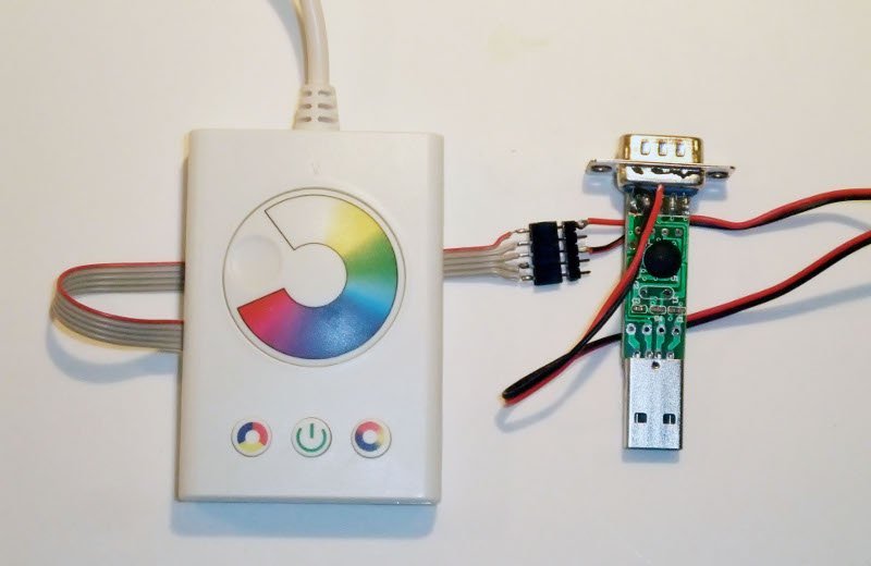
The Dioder (3-button version) consists of a power supply, 4 led bars each containing 9 pretty bright RGB LEDs, some fixtures and a control unit. The interesting part is the control unit, which is build around a Microchip PIC16F684 microcontroller. The PIC generates 3 PWM signals (Red, Green and Blue) which are amplified by 3 FETs, to power the RGB LEDs. A potmeter is connected to an AD convertor attached to a colorwheel. There are also 3 buttons attached to GPIO lines.
So I hooked up my old oscilloscope to the Dioder to see what Ikea's software was capable of. It turns out that rotating the color wheel, only fades one channel at a time (the other two are kept either on or off). The PWM period is exactly 1kHz and is divided in 20 steps (providing 21 intensities, including black/off).
My goals
What I wanted to achieve, was a simple and cheap solution, providing ambient lighting for your mediacenter. I also wanted to keep the hardware modifications to a minimum, in order to keep this solution accessible to (almost) everyone.
The quality of the lighting has to be good in terms of number of colors and frequency. Also the interface to the mediacenter has to be very responsive and reliable.
The hardware
To turn your Dioder into an Ambioder, all you need to do is solder the ICSP port (5 wires) onto the Dioder PCB and reprogram it. The hex file for reprogramming can be downloaded here.
To communicate with your Ambioder, you will need a USB TTL-RS232 adapter (like this one, or this one).
Connect the USB-RS232 controller to the ICSP port you previously soldered to the Dioder PCB. Pin 5 of the serial port (gnd) goes to pin 3 (Vss) of the ICSP port. Pin 3 of the serial port (tx) goes to pin 1 (Vpp) of the ICSP.
Alternatively, you can use a CHEAP USB serial port, like I did; The reason it has to be cheap, is because the higher quality ones contain an RS-232 level-shifter. The -5 to -15V signal generated by the level-shifter could damage the microcontroller! You will need this version of the Ambioder firmware for use with a USB serial port.
 WARNING: Do not use the serial port on your motherboard, it most certainly contains a level-shifter!
The PIC software
The PIC software was a lot more difficult; the PIC16F684 does not contain a UART controller, it also does not contain a PWM controller. Since I want the UART to be 100% reliable and the PWM to be 100% stable, the absence of these components provided a challenge.
Luckily the PIC16F684 does come with an interrupt controller and a timer/comparator interrupt source, I use this to poll the serial port and step the PWM at a regular interval.
Ambioder uses the PIC16F684 internal oscillator at 8Mhz, resulting in 2 million instructions per second. This might sound like a lot, but is actually pretty tight...
Design
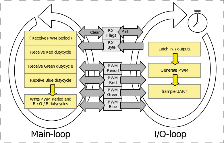
I designed the PIC software to run as two concurrent loops.
The IO-loop is executed with every timer interrupt. It starts by latching the I/O pins (to ensure constant timing), it then steps the PWM generator and samples the UART RX-line.
The main-loop gathers the received bytes from the UART. After a complete sequence is received, it will pass the received PWM period and R/G/B dutycycles PWM generator.
These two loops interface with each-other using a few shared variables.
Serial protocol
The main-loop will look for a sequence of the following bytes (hex):[0x0X 0x1X] 0x2X 0x3X 0x4X 0x5X 0x6X 0x7X
The most significant nibble contains the address, the least significant nibble contains the data
- address 0: pwm period, most significant nibble
- address 1: pwm period, least significant nibble
- address 2: pwm red, most significant nibble
- address 3: pwm red, least significant nibble
- address 4: pwm green, most significant nibble
- address 5: pwm green, least significant nibble
- address 6: pwm blue, most significant nibble
- address 7: pwm blue, least significant nibble
The PWM period is optional and will remain unchanged if it was not received. After receiving the entire sequence, the PWM period and Red/Green/Blue values are passed to the PWM generator and the main-loop restarts. Every UART error or unexpected RX byte, will result in the main-loop restarting.
Implementation
My implementation provides a UART receiver, an RGB PWM generator and a main-loop implementing my protocol.
The UART receiver functions at 19200/8N1, with a 1-byte buffer.
The RGB PWM generator can generate anything from 16 Million colors at 224Hz, to 4096 colors at 3.8kHz. The PWM generator is also buffered, so it will never flicker when changing colors.
The boblight implementation
To control the Ambioder device, I extended the Boblight project with Ambioder support.
The result
I have installed the Ambioder on my mediacentre and tested it for a few days now. I am very pleased with the results. It works reliable, the PWM frequency is good and it produces very nice colors.
Excited about Ambioder? Buy me a beer!